What Did I Do This Week?
Testing and Debugging
Given the lack of direct methods to test the correctness of rendered circuits, I had to employ various combinations and scenarios to identify any breaking points in the code or logic. This week, I encountered and resolved two significant issues:
- Rendering Logic Flaw for Custom Gates with Multiple Control Nodes: I identified a flaw in the rendering logic for custom gates that involved multiple control wires and worked on fixing this issue to ensure proper visualization.
- Dynamic Gate Sizing with Text Input: There was a previously mentioned problem with dynamically adjusting gate sizes when text input was involved. This issue has also been resolved, ensuring that gate sizes adjust correctly based on the text they contain.
Styling Customization Integration
The goal for this week was to integrate styling customization with the current gate class and implement the global-dense option to allow users to shrink the size of the circuit.
Currently, the gate class accepts a styling dictionary as input with the following customization parameters:
text: Custom gate labelcolor: Controls gate background colorfontsize: Size of the textfontcolor: Controls the font color of the textfontweight: Controls the weight of the font styles | “bold”, “normal” (default) | custom valuefontfamily: ‘serif’ | ‘sans-serif’ | ‘cursive’ | ‘fantasy’ | ‘monospace’ (default)fontname: Custom font integration (yet to test)
Here is an example of user customization options: 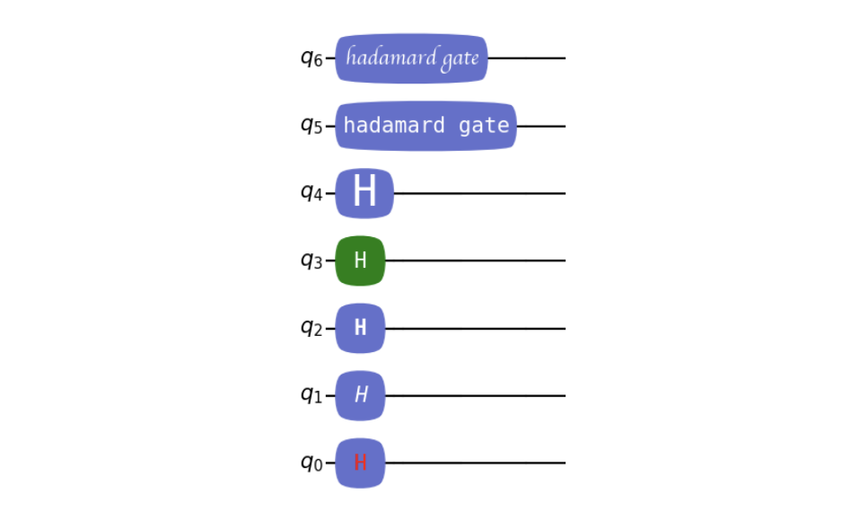
Global-Dense Feature
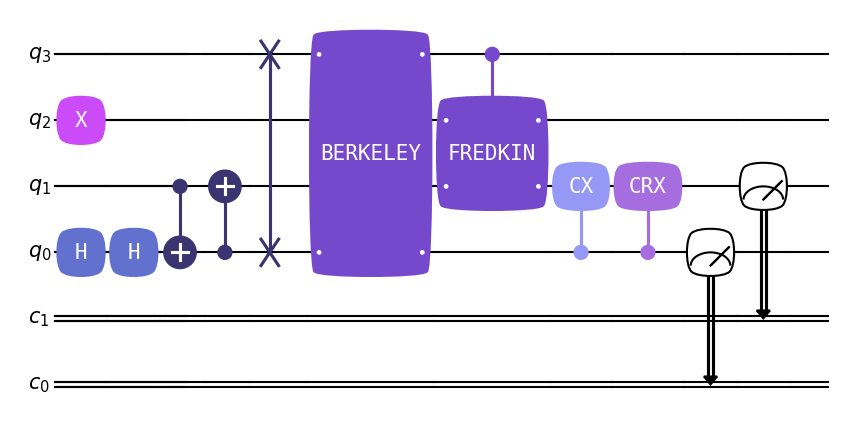
The global-dense feature, specified by the condense argument in the MatRenderer class, allows users to shrink the size of the circuit. The images below demonstrate the default setting and the condense = 0.1 setting, respectively:
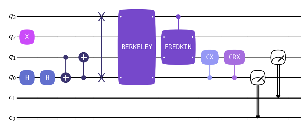
Addition of Connectors for Multi-Qubit Gates
Another important improvement was the addition of connectors for multi-qubit gates. In cases where there are multiple targets of a multi-qubit gate, connectors are added to the gate graphic to identify which wire it is connecting to. This ensures clarity, especially when the gate is drawn over wires it is not connected to. Example can be seen in above “BERKELEY” Gate.
Plan for next week ?
- Add option to display gate argument in label
- multiline row support for gate label
- Make a Draft PR
- Notebook Tutorials
- Find / Fix bugs